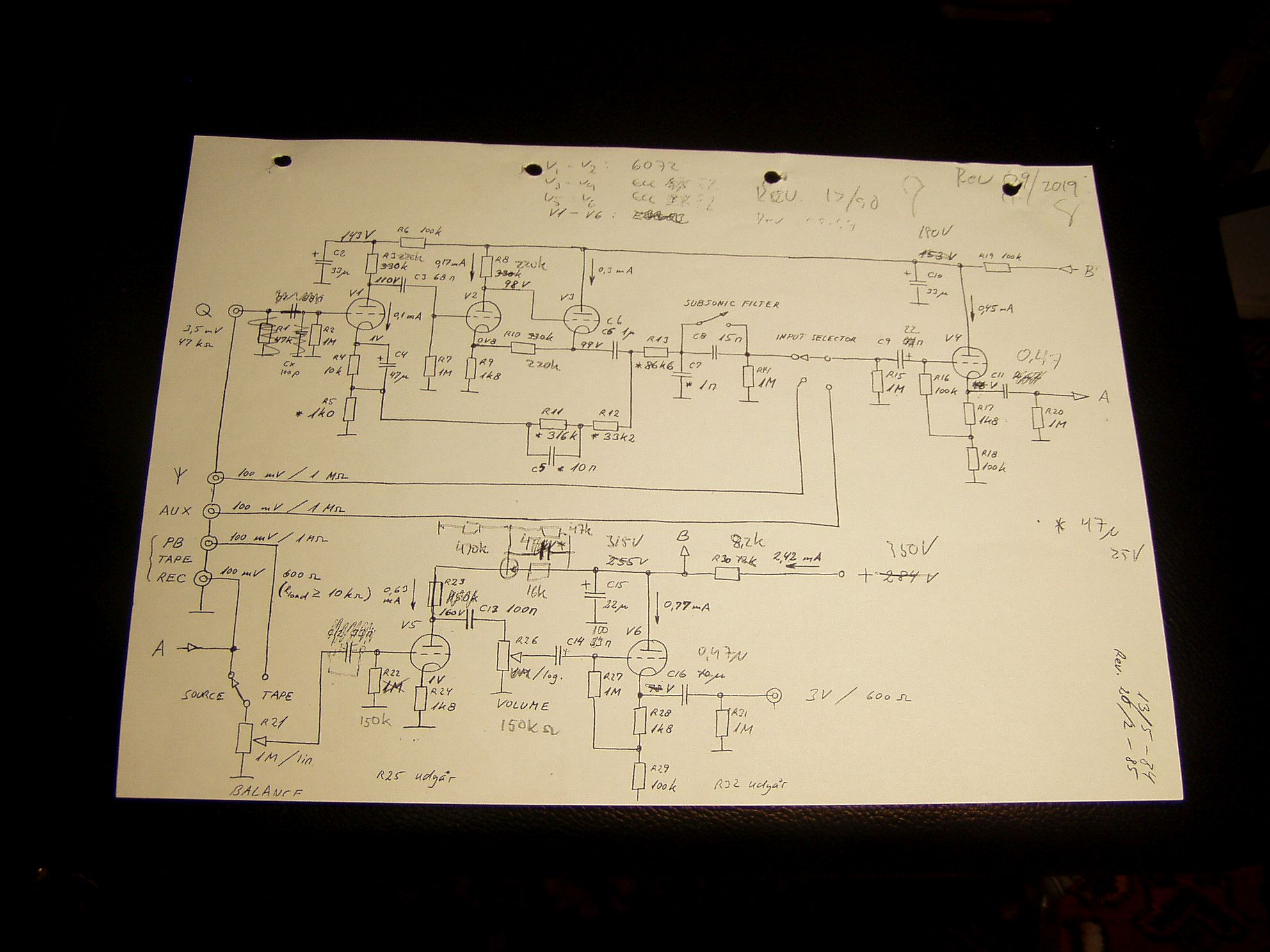
My first tube/valve preamp was based on a McIntosh preamp design, probably from around 1950. A great deal of help also came from a friend, Claus Sorensen. Original diagram dates back to 1984, and my last revision was in 2020.
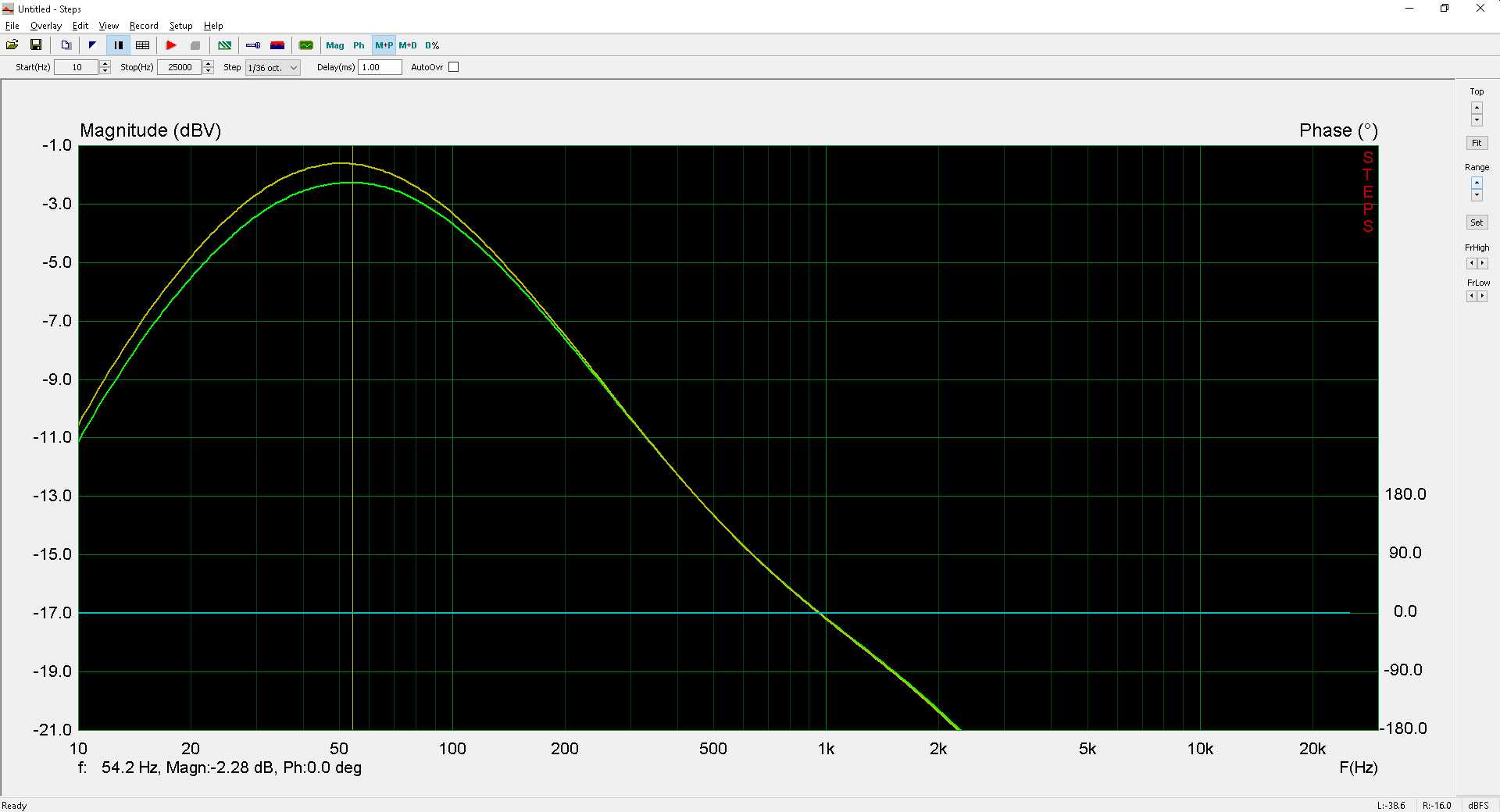
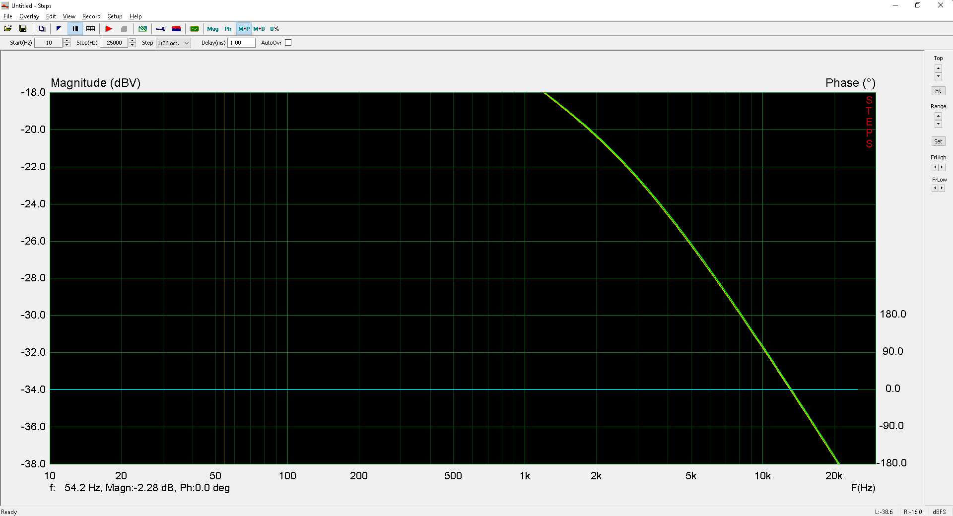
There are some fine design elements in the original diagram. One is the way the RIAA correction is implemented – active bass correction in a feedback loop, passive treble correction. The components used here should be 1% tolerance. Another feature is the long power supply line with a number of R – C voltage reducing steps, also good for noise and hum rejection. In the beginning, all tubes were ECC83 / 12 AX7. Due to the need for input buffering, there are a number of cathode followers, too many for SOTA reproduction, but a sensible approach for real life conditions. Amplifier inverts the absolute phase, due to the single anode follower in the last stage.
During the years, I have modified a number of things. Input impedance, designed for moving magnet pickups, is removed since I use a separate moving coil amp, and this one needs a high impedance load. Many input safety
capacitors are removed, too many R – C combinations affects bottom end reproduction and, to a small extent, low end linearity, they introduce a roll-off. For the last stage, anode resistor was replaced with a constant current generator, to get maximum voltage gain from the stage. Volume is a series attenuator, with 23 steps. Total resistance is 150 K Ohms. Capacitors: I like the paper-in-oil type, excellent for high voltage, thermally stable and close to everlasting, can't remember one single capacitor going down! Measure them for critical use, and parallel to correct value if needed.
Tubes have changed during the years, see today's circuit diagram for present types. I abandoned ECC 83 many years ago, I find them nice to listen to, they create a warm and non-edgy sound, but lack detail, clarity and top end freedom. Too much coloration for objective monitoring use.
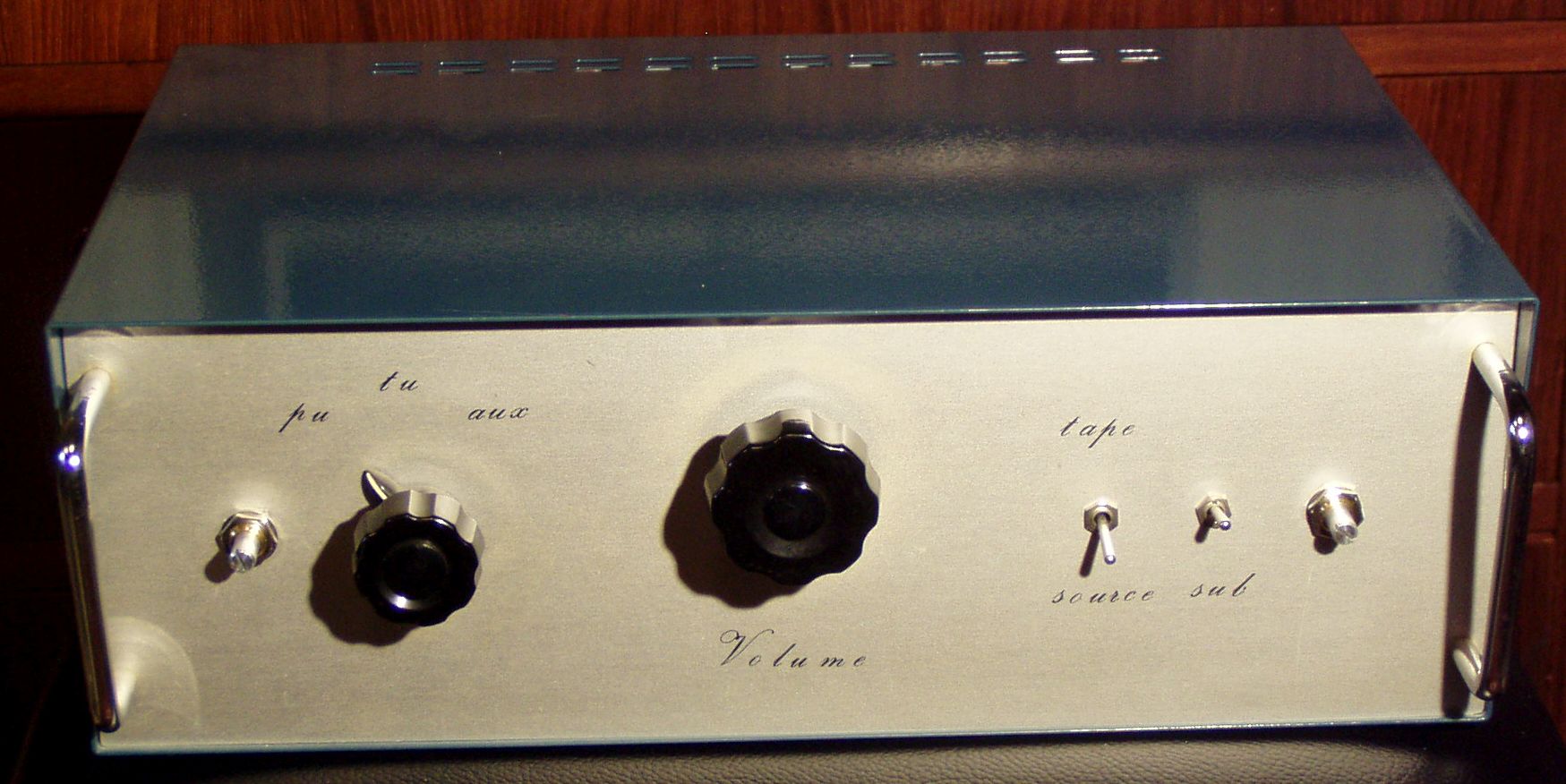
During the entire life of the amplifier, (36 years!!) it has functioned without any sort of breakdown or component failure. High quality sound reproduction, and no listening fatigue whatsoever. Mains transformer / power supply is standard, and has it's own cabinet, power for the heaters is DC, 6.3 V and I use a simple, discrete regulator.
The last revision took place in 2020, and included RIAA and line stage, see Microcap diagram for today's component values. Original diagram at bottom of page.


stealthe idea from someone else!! This was in 1984!!. Worked perfectly, print is double sided, and the ground plane is under/ at the other side of the print – only holes for ground connection. O-rings on input tubes to reduce microphony. A perforated metal shield is another option. Volume attenuator, quality caps, 1 % components, conservative component selection ensures stable function for many years.


normallistening level.