This regulated PSU goes a long way back. In the beginning, it was used, and designed, for a Hiraga moving coil amplifier. General demands were: very low noise, small currents (10 - 50 mA) and around +/- !5 Volts.
Credits for the general design goes to a friend, Jakob Ertner, and it dates back to something like 1990.
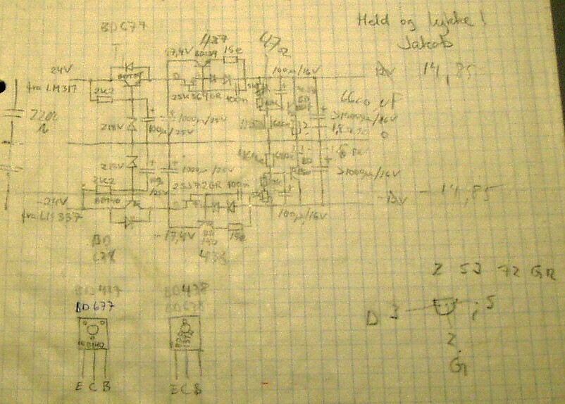
Today, the circuit has not changed much, new casing and connectors, and mains transformer. See pictures! Use the diagram as inspiration, components can be changed and/or upgraded. The use of 2SJ72/2SK369GR is important though, since it is a low noise type FET. Discrete transistors can be hard to find today, and I don't know if there are alternatives/upgrades. Bipolar transistors are less critical, I used BD677 and BD678 due to their voltage and current rating, limits are far away from what they are exposed to in this circuit.
Input voltage comes from 2 standard regulators, LM317 and LM337, not very clear on the diagram!!
The interesting things about the diagram is the combination of series and parallel regulation. Today, maybe/probably some SOTA IC:s, (there are both serial and parallel regulators on the market) would do a better job, either alone or as a combination. In this diagram, layout allows me to end up with a capacitor power reserve AFTER the regulation, there are 6600 uF at the very end, and that is a good thing, both for noise and available transient current.
Regulation is fine, after warm-up, it delivers stable +/- 14.85 Volts and ample current to drive a number of IC:s, depending on current demands.